iHF High-Sensitivity Diaphragm Coupling Servo Stepper Motor Elastic Coupling
Send Inquiry Now


 EN
EN
 Request Quote
Product features:
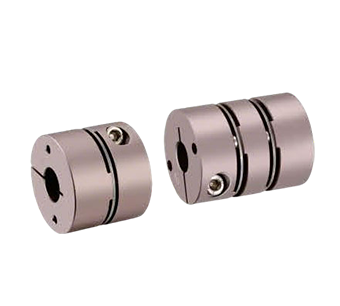
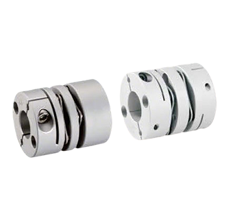
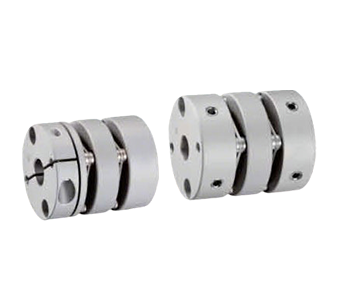
Screw Clamping Type Aluminum Alloy Circular Diaphragm Coupling
1. Core Materials
- Hub: High-strength aviation-grade aluminum alloy (T6 heat treated, tensile strength ≥400MPa)
- Diaphragm: 304 stainless steel (mirror polished, surface roughness Ra≤0.8μm)
2. Key Performance Characteristics
- Ultra-high torsional rigidity (stiffness coefficient ≥5000Nm/rad), achieves ±0.01° rotational positioning accuracy
- Zero-backlash connection structure (radial runout ≤0.02mm), ensures no lost motion in bidirectional transmission
- Optimized inertia design (moment of inertia <0.001kg·m²), maximum rotational speed up to 8000rpm
3. Engineering Design Features
- Specifically matched for high-precision servo/stepper motors (compatible with 50W-5kW motor power range)
- Utilizes Grade 8.8 high-strength alloy steel clamping screws (adjustable preload, anti-loosening design)
- Diaphragm assembly employs laser welding technology, compensating for angular misalignment ±3° and axial misalignment ±0.5mm
4. Typical Applications
- Industrial robots (6-axis joints, SCARA arms)
- High-end CNC machine tools (5-axis machining centers)
- Semiconductor equipment (wafer handling robots)
- Precision measuring instruments (optical inspection platforms)
| Model | L | Allowable Torque (N·m) | Allowabl eMisalignment (Radial)(mm) | Allowable Angular Misalignment (<°) | Allowable Axial Displacement(mm) | Maximu mAllowable Speed (RPM) | Stati cTorsional Stiffness (N.m/rad) | Moment o fInertia (N.m) | Coupling Weight(g) | |
| Type | D | |||||||||
| QLNAW | 19 | 27 | 1 | 0.15 | 2 | ±0.20 | 15000 | 450 | 6.7×10⁻⁷ | 20 |
| 25 | 31 | 2 | 0.2 | 2 | ±0.40 | 10000 | 850 | 2.3×10⁻⁶ | 38 | |
| 32 | 40 | 4.2 | 0.25 | 2 | ±0.60 | 10000 | 1600 | 9.0×10⁻⁶ | 80 | |
| 40 | 44 | 8 | 0.3 | 2 | ±0.60 | 10000 | 3200 | 2.1×10⁻⁵ | 120 | |
| 50 | 57 | 10 | 0.3 | 2 | ±0.60 | 10000 | 3900 | 3.5×10⁻⁵ | 160 | |
| QSNAW | 19 | 20 | 1 | 0.02 | 1 | ±0.10 | 15000 | 600 | 2.9×10⁻⁷ | 13 |
| 25 | 24 | 2 | 0.02 | 1 | ±0.20 | 15000 | 1300 | 1.1×10⁻⁶ | 25 | |
| 28 | 28 | 2.2 | 0.02 | 1 | ±0.20 | 10000 | 1600 | 1.4×10⁻⁶ | 34 | |
| 32 | 29 | 4.2 | 0.02 | 1 | ±0.30 | 10000 | 2500 | 4.0×10⁻⁶ | 57 | |
| 40 | 33 | 8 | 0.02 | 1 | ±0.30 | 10000 | 4600 | 9.8×10⁻⁶ | 86 | |
| 50 | 42 | 15 | 0.02 | 1 | ±0.30 | 10000 | 6000 | 1.6×10⁻⁵ | 130 | |
The inner bores on both ends of the coupling can be freely combined between minimum and maximum diameters, machined to H7 standard tolerance. Bore dimensions listed in tables are for reference only; for custom bore requirements, please contact our customer support, sales representatives, or technical personnel for detailed parameters.
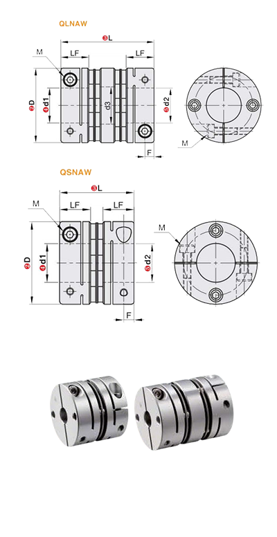
| Model | L | d1,d2(Keyway bore diameters are selectable for sizes above 6mm.) | LF | φd3 | F | M | Fastening Torque (N.m) | ||
| Type | D | Double Diaphragm | Single Diaphragm | ||||||
| QLNAW QSNAW | 19 | 27 | 20 | *3 4 5 6 6.35 7 8 | 9.2 | 9.5 | 3.3 | M2.5 | 0.8 |
| 25 | 31 | 24 | *3 *4 5 6 6.35 7 8 9 9.525 10 11 12 | 10 | 12.56 | 3.9 | M3 | 1.2 | |
| 28 | - | 28 | *3 *4 *5 6 6.35 7 8 9 9.525 10 11 12 12.7 | 11 | 14.5 | 3.9 | M3 | 1.2 | |
| 32 | 40 | 29 | *3 *4 *5 *6 *6.35 *7 *8 9 9.525 10 11 12 12.7 14 15 16 | 12 | 16 | 4.5 | M3 | 2.5 | |
| 40 | 44 | 33 | 8 9 9.525 10 11 12 12.7 14 15 16 17 18 19 | 14 | 19.3 | 5 | M4 | 2.5 | |
| 50 | 57 | 42 | 8 9 9.525 10 11 12 12.7 14 15 16 17 18 19 20 22 24 | 18 | 23 | 5 | M4 | 2.5 | |
The moment of inertia and all technical parameters provided are measured with the maximum bore size as the reference standard. The maximum rated torque correlates directly with the coupling's fatigue life. Larger outer diameters increase load capacity, while smaller outer diameters permit higher maximum allowable speeds.
QLNAW series: Specifications marked with ✳ symbol are not selectable.
| Model | Type | Material | Surface Treatment | Accessories | |
| Housing | Diaphragm | ||||
| QLNAW | Double Diaphragm | Aluminum Alloy | Stainless Steel | Anodized | Socket Head Cap Screw(SHCS) |
| QSNAW | Single Diaphragm | ||||