iHF Factory Outlet Double Diaphragm Coupling Shaft Couplers for Shaft
Send Inquiry Now


 EN
EN
 Request Quote
Product features:
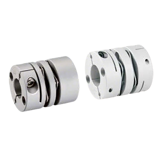
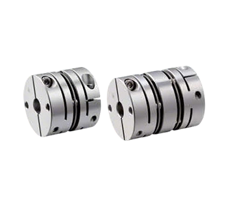
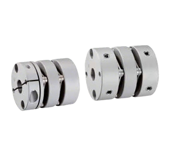
Partial Skew Cut Clamp Coupling Aluminum Alloy High-Sensitivity Diaphragm Coupling
1.Materials & Manufacturing
- High-Strength Aluminum Alloy Body: Lightweight design with structural integrity. Surface customizable with anodizing or pearl nickel plating for enhanced corrosion resistance and aesthetics.
- Stainless Steel Core Diaphragm: High rigidity and fatigue resistance, precisely compensating for angular and axial misalignment to ensure long-term operational stability.
2.Key Performance
-Exceptional Torsional Rigidity: Enables precise rotational control of shafts, ideal for high-precision transmission applications.
- Ultra-Low Inertia & High Sensitivity**: Delivers rapid response and supports high-speed operation with superior dynamic performance.
- Bidirectional Symmetry: Identical rotational characteristics in both clockwise and counterclockwise directions, ensuring consistent motion control.
3.Application Advantages
- Precision Industrial Equipment: Suitable for demanding fields such as robotic joints, optical instruments, and semiconductor equipment where accuracy and speed are critical.
- Longevity-Optimized Design: Stainless steel diaphragm resists wear, while the aluminum alloy body minimizes deformation, significantly reducing maintenance costs.
| Model | L | Allowable Torque (N·m) | Allowable Misalignment (Radial)(mm) | Allowable Angular Misalignment (<°) | Allowable Axial Displacement (mm) | Maximum Allowable Speed (RPM) | Static Torsional Stiffness (N.m/rad) | Moment of Inertia (N.m) | Coupling Weight (g) | |
| Type | D | |||||||||
QLFCAW | 16 | 23.2 | 0.9 | 0.15 | 2 | ±0.20 | 6000 | 450 | 2.7×10⁻⁷ | 12 |
| 20 | 26 | 1.3 | 0.15 | 2 | ±0.20 | 5500 | 700 | 8.0×10⁻⁷ | 26 | |
| 25 | 30.2 | 2.8 | 0.15 | 2 | ±0.30 | 5000 | 950 | 7.6×10⁻⁵ | 45 | |
| 32 | 41 | 5 | 0.15 | 2 | ±0.40 | 4000 | 1100 | 2.5×10⁻⁶ | 73 | |
| 40 | 47 | 9 | 0.2 | 2 | ±0.50 | 3800 | 2800 | 1.9×10⁻⁵ | 100 | |
| 50 | 53 | 16 | 0.2 | 2 | ±0.60 | 3500 | 3400 | 5.0×10⁻⁴ | 193 | |
| QSECAW QSECAW | 16 | 16.5 | 0.9 | 0.1 | 1 | ±0.10 | 6000 | 650 | 2.2×10⁻⁷ | 8 |
| 20 | 18.4 | 1.3 | 0.1 | 1 | ±0.10 | 5500 | 950 | 7.0×10⁻⁷ | 13 | |
| 25 | 21.6 | 2.8 | 0.1 | 1 | ±0.20 | 5000 | 1300 | 2.2×10⁻⁶ | 24 | |
| 32 | 29 | 5 | 0.1 | 1 | ±0.20 | 4000 | 1400 | 5.0×10⁻⁶ | 53 | |
| 40 | 35 | 9 | 0.15 | 1 | ±0.20 | 3800 | 3300 | 1.5×10⁻⁵ | 90 | |
| 50 | 41 | 16 | 0.15 | 1 | ±0.30 | 3500 | 4000 | 3.9×10⁻⁵ | 180 | |
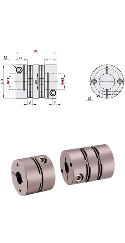
The inner bores on both ends of the coupling can be freely combined between minimum and maximum diameters, machined to H7 standard tolerance. Bore dimensions listed in tables are for reference only; for custom bore requirements, please contact our customer support, sales representatives, or technical personnel for detailed parameters.
| Model | L | d1,d2(Keyway bore diameters are selectable for sizes above 6mm.) | LF | φd3 | F | M | Fastening Torque (N.m) | ||
| Type | D | Double Diaphragm | Single Diaphragm | ||||||
QLFCAW | 16 | 23.2 | 16.5 | 3 4 4.5 5 6 | 8 | 6.8 | 3 | M2.5 | 1 |
| 20 | 26 | 18.4 | 4 5 6 6.35 7 8 | 9 | 8.1 | 3.7 | M2.5 | 1 | |
| 25 | 30.2 | 21.6 | 5 6 6.35 7 8 9 9.525 10 | 10.5 | 10.4 | 4 | M3 | 1.7 | |
| 32 | 41 | 29 | 8 9 9.525 10 11 12 12.7 14 | 14.05 | 15 | 6 | M4 | 2.5 | |
| 40 | 47 | 35 | 8 9 9.525 10 11 12 12.7 14 15 16 17 18 | 16.9 | 19.5 | 7.8 | M4 | 7 | |
| 50 | 53 | 41 | 10 11 12 12.7 14 15 16 17 18 19 20 22 24 | 19.75 | 25 | 9 | M5 | 12 | |
The moment of inertia and all technical parameters provided are measured with the maximum bore size as the reference standard. The maximum rated torque correlates directly with the coupling's fatigue life. Larger outer diameters increase load capacity, while smaller outer diameters permit higher maximum allowable speeds.
| Model | Type | Material | Surface Treatment | Accessories | ||
| Housing | Diaphragm | |||||
| QLFCAW | Partial Skew Cut Clamp Coupling | Double Diaphragm | Aluminum Alloy | Stainless Steel | Anodized | Socket Head Cap Screw(SHCS) |
| QSECAW | Single Diaphragm | |||||
| QLFCAN | Double Diaphragm | Pearl Nickel Plated | ||||
| QSECAN | Single Diaphragm | |||||