iHF High Quality Aluminum Alloy Stainless Steel Motor Shaft Couplings
Send Inquiry Now


 EN
EN
 Request Quote
Product features:
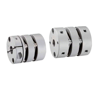
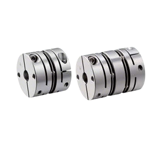
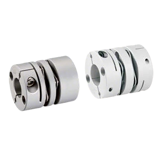
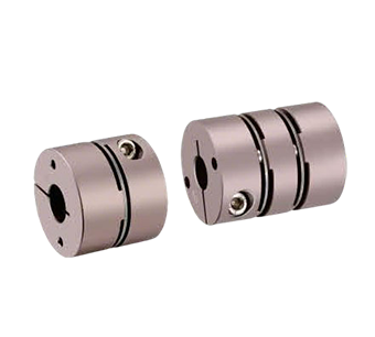
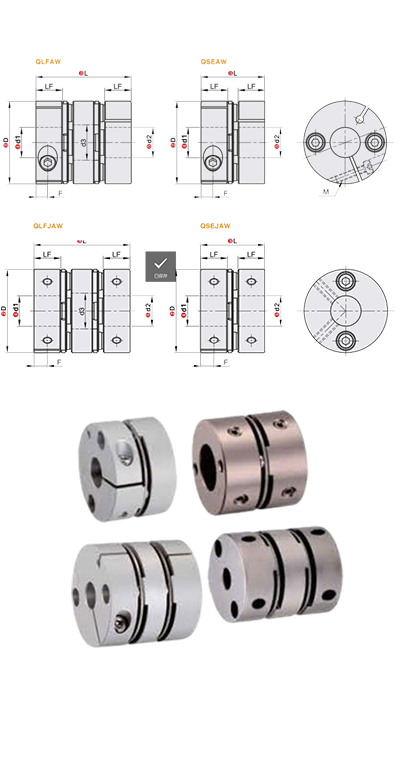
Screw Clamping/Fixing Type Aluminum Alloy High-Sensitivity Diaphragm Coupling
1. Core Materials
- Hub: High-strength aluminum alloy (lightweight design with balanced structural strength and corrosion resistance)
- Diaphragm: 304 stainless steel (high rigidity, fatigue resistance for long-term stable operation)
2. Key Performance Characteristics
- High torsional rigidity: Enables precise shaft rotation control for high-precision transmission applications
- Zero-backlash connection: Clearance-free hub-shaft coupling ensures no hysteresis in bidirectional operation
- Low-inertia design: Optimized dynamic response for high-speed operation
- Bidirectional symmetry: Identical rotational characteristics in CW/CCW directions for stable motion control
3. Engineering Design Features
- Motor compatibility: Specifically optimized for servo and stepper motors to enhance system integration
- Misalignment compensation: Stainless steel diaphragm effectively absorbs angular and axial misalignment, reducing installation precision requirements
- Fastening method: High-strength clamping screws ensure reliable connection (optional anti-loosening design available)
4. Typical Applications
- Industrial robotic joint modules
- CNC machine tool spindle drives
- Precision automation equipment (e.g.SMT machines, laser cutters)
- Medical/optical instrument drive systems
| Model | L | Allowable Torque (N·m) | Allowable Misalignment (Radial) (mm) | Allowable Angular Misalignment (<°) | Allowable Axial Displacement (mm) | Maximum Allowable Speed (RPM) | Static Torsional Stiffness (N.m/rad) | Moment of Inertia (N.m) | Coupling Weight (g) | |
| Type | D | |||||||||
| QLFAW | 16.6 | 23 | 0.5 | 0.1 | 1 | ±0.18 | 9000 | 480 | 4.22×10⁻⁷ | 12 |
| 21 | 24.5 | 1 | 0.1 | 1 | ±0.18 | 8000 | 750 | 1.11×10⁻⁶ | 18 | |
| 28 | 32.2 | 1.5 | 0.15 | 1.2 | ±0.18 | 8000 | 2500 | 4.68×10⁻⁶ | 45 | |
| 34 | 35 | 4 | 0.17 | 1.5 | ±0.18 | 8000 | 4200 | 1.11×10⁻⁵ | 70 | |
| 46 | 44 | 9 | 0.22 | 1.5 | ±0.25 | 8000 | 11000 | 3.8×10⁻⁵ | 144 | |
| 55 | 55 | 25 | 0.25 | 1.5 | ±0.25 | 8000 | 16500 | 1.6×10⁻⁴ | 265 | |
| QSEAW | 16 | 16.6 | 0.5 | 0.1 | 1 | ±0.09 | 9000 | 950 | 3.16×10⁻⁷ | 8 |
| 21 | 16.7 | 1 | 0.1 | 1 | ±0.14 | 8000 | 1600 | 7.9×10⁻⁷ | 13 | |
| 28 | 21.5 | 1.5 | 0.1 | 1.2 | ±0.18 | 8000 | 5500 | 3.24×10⁻⁶ | 32 | |
| 34 | 23.3 | 3 | 0.1 | 1.5 | ±0.18 | 8000 | 7500 | 7.6×10⁻⁶ | 50 | |
| 46 | 29.8 | 9 | 0.1 | 1.5 | ±0.27 | 8000 | 18000 | 3.23×10⁻⁵ | 102 | |
| 55 | 37.2 | 25 | 0.1 | 1.5 | ±0.30 | 8000 | 30000 | 8.19×10⁻⁵ | 180 | |
| QLFJAW | 16 | 23.2 | 0.9 | 0.15 | 2 | ±0.20 | 6000 | 450 | 2.7×10⁻⁷ | 12 |
| 20 | 26 | 1.3 | 0.15 | 2 | ±0.20 | 5500 | 700 | 8.0×10⁻⁷ | 26 | |
| 25 | 30.2 | 2.8 | 0.15 | 2 | ±0.30 | 5000 | 950 | 2.5×10⁻⁶ | 45 | |
| 32 | 41 | 5 | 0.15 | 2 | ±0.40 | 4000 | 1100 | 6.6×10⁻⁶ | 73 | |
| 40 | 47 | 9 | 0.2 | 2 | ±0.50 | 3800 | 2800 | 1.9×10⁻⁵ | 100 | |
| 50 | 53 | 16 | 0.2 | 2 | ±0.60 | 3500 | 3400 | 5.0×10⁻⁴ | 193 | |
| QSEJAW | 16 | 16.5 | 0.9 | 0.1 | 1 | ±0.10 | 6000 | 650 | 2.2×10⁻⁷ | 8 |
| 20 | 18.4 | 1.3 | 0.1 | 1 | ±0.10 | 5500 | 950 | 7.0×10⁻⁷ | 12 | |
| 25 | 21.6 | 2.8 | 0.1 | 1 | ±0.20 | 5000 | 1300 | 2.2×10⁻⁶ | 24 | |
| 32 | 29 | 5 | 0.1 | 1 | ±0.20 | 4000 | 1400 | 5.6×10⁻⁶ | 53 | |
| 40 | 35 | 9 | 0.15 | 1 | ±0.20 | 3800 | 3300 | 1.5×10⁻⁵ | 90 | |
| 50 | 41 | 16 | 0.15 | 1 | ±0.30 | 3500 | 4000 | 3.9×10⁻⁵ | 180 | |
The inner bores on both ends of the coupling can be freely combined between minimum and maximum diameters, machined to H7 standard tolerance. Bore dimensions listed in tables are for reference only; for custom bore requirements, please contact our customer support, sales representatives, or technical personnel for detailed parameters.
| Model | L | d1,d2(Keyway bore diameters are selectable for sizes above 6mm.) | LF | φd3 | F | M | Fastening Torque (N.m) | ||
| Type | D | QLFAW | QSEAW | ||||||
| QLFAW QSEAW | 16 | - | 16.6 | 3 4 4.5 5 6 | 8 | 6.5 | 3.3 | M2.5 | 0.8 |
| 16.6 | 23 | - | 3 4 4.5 5 6 | 8 | 6.5 | 3.3 | M2.5 | 0.8 | |
| 21 | 24.5 | 16.7 | 4 5 6 6.35 7 8 | 8 | 10.5 | 3.3 | M2.5 | 0.8 | |
| 28 | 32.2 | 21.5 | 5 6 6.35 7 8 9 9.525 10 | 10.4 | 15 | 3.85 | M3 | 1.2 | |
| 34 | 35 | 23.3 | 8 9 9.525 10 11 12 12.7 14 | 11.2 | 16.5 | 4.85 | M4 | 2.5 | |
| 46 | 44 | 29.8 | 8 9 9.525 10 11 12 12.7 14 15 16 17 18 | 14.3 | 25.5 | 5 | M5 | 5 | |
| 55 | 55 | 37.2 | 10 11 12 12.7 14 15 16 17 18 19 20 22 24 | 17.8 | 31 | 6 | M5 | 5 | |
| 模式 | L | d1,d2(Keyway bore diameters are selectable for sizes above 6mm.) | LF | φd3 | F | M | Fastening Torque (N.m) | ||
| 模型 | D | QLFJAW | QSEJAW | ||||||
| QLFJAW QSEJAW | 16 | 23.2 | 16.5 | 3 4 4.5 5 6 | 7 | 6.8 | 3 | M2.5 | 1 |
| 20 | 26 | 18.4 | 3 4 5 6 6.35 7 8 9 9.525 10 | 7.5 | 8.1 | 3.7 | M2.5 | 1 | |
| 25 | 30.2 | 21.6 | 5 6 6.35 7 8 9 9.525 10 11 12 12.7 14 | 9 | 10.4 | 4 | M3 | 1.7 | |
| 32 | 41 | 29 | 5 6 6.35 7 8 9 9.525 10 11 12 12.7 14 15 16 | 12.4 | 15 | 6 | M4 | 2.5×10⁻⁴ | |
| 40 | 47 | 35 | 9 9.525 10 11 12 12.7 14 15 16 17 18 19 20 22 24 25 | 15.5 | 19.5 | 7.8 | M5 | 7 | |
| 50 | 53 | 41 | 10 11 12 12.7 14 15 16 17 18 19 20 22 24 25 28 30 | 18 | 20 | 9 | M6 | 12 | |
The moment of inertia and all technical parameters provided are measured with the maximum bore size as the reference standard. The maximum rated torque correlates directly with the coupling's fatigue life. Larger outer diameters increase load capacity, while smaller outer diameters permit higher maximum allowable speeds.
| Model | Type | Material | Surface Treatment | Accessories | ||
| Housing | Diaphragm | |||||
| QLFAW | Single Diaphragm | Screw Clamping Type | Aluminum Alloy | Stainless Steel | Anodized | Socket Head Cap Screw(SHCS) |
| QLFJAW | Cross-Pinned Set Screw Fixation | Hex Socket Set Screw | ||||
| QSEAW | Double Diaphragm | Screw Clamping Type | Socket Head Cap Screw(SHCS) | |||
| QSEJAW | Cross-Pinned Set Screw Fixation | Hex Socket Set Screw | ||||