 EN
EN en
en vi
vi it
it es
es th
th tr
tr ja
ja pt
pt ko
ko ru
ru fr
fr de
de ar
ar Request Quote
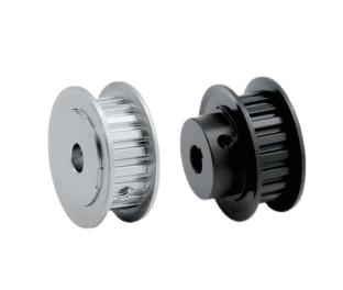
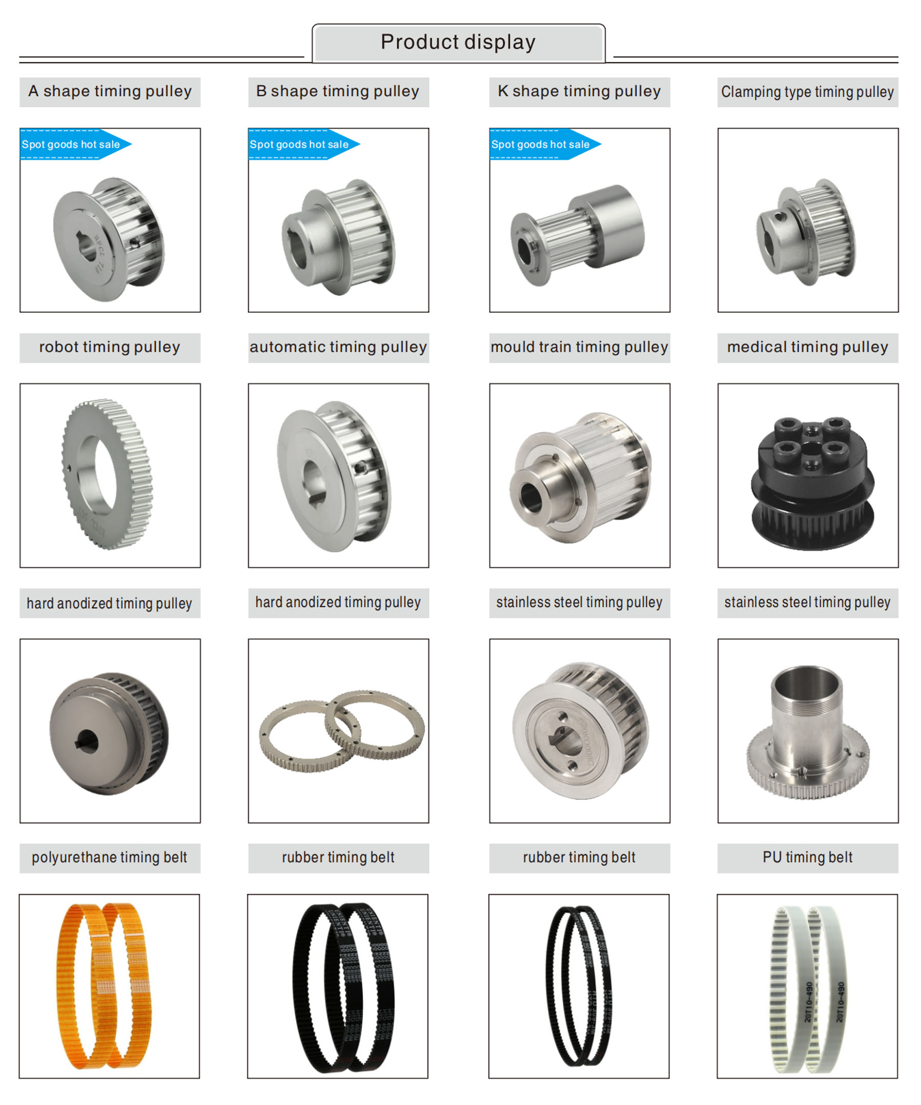
iHF Timing Pulley Power Transmission Light-Duty Conveying MXL/XL/L/H
Send Inquiry Now
Productfeatures:
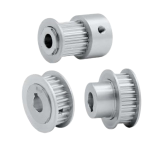
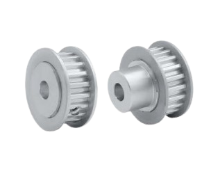
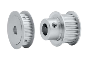
Heavy-duty power transmission synchronous pulleys are built with high-strength, wear-resistant materials such as alloy steel and aluminum alloy, ensuring durability under high loads and high speeds. Manufactured to strict precision standards, they maintain accurate tooth profiles and pitch, improving transmission accuracy and stability.
To accommodate diverse industrial needs, these pulleys are available in multiple designs, including various tooth profiles, pitches, diameters, and widths. Their toothed engagement with timing belts enables highly efficient power transmission—typically above 0.98—while ensuring non-slip operation and precise transmission ratios essential for controlled speed and torque.
The AT-Series reinforced trapezoidal timing pulleys, an upgraded version of T-Series technology, feature strengthened tooth geometry and enhanced materials. They deliver superior reliability and performance in heavy-duty and high-torque industrial environments.


| Model | Synchronous pulley for heavy-duty power transmission |
| Material | 6061/S45C |
| Module | AT5/AT10 |
| Shape | A/B/D/E/F/K |
| Transport Package | Each item should be packed in a polyethylene bag or wax paper and placed in one or more boxes. |
| Trademark | iHF |
| HS Code | 8448399000 |
| Manufacturing Process | Casting |
| Surface Treatment | Electroplating |
| Surface Color | Clear/Black/Silver |
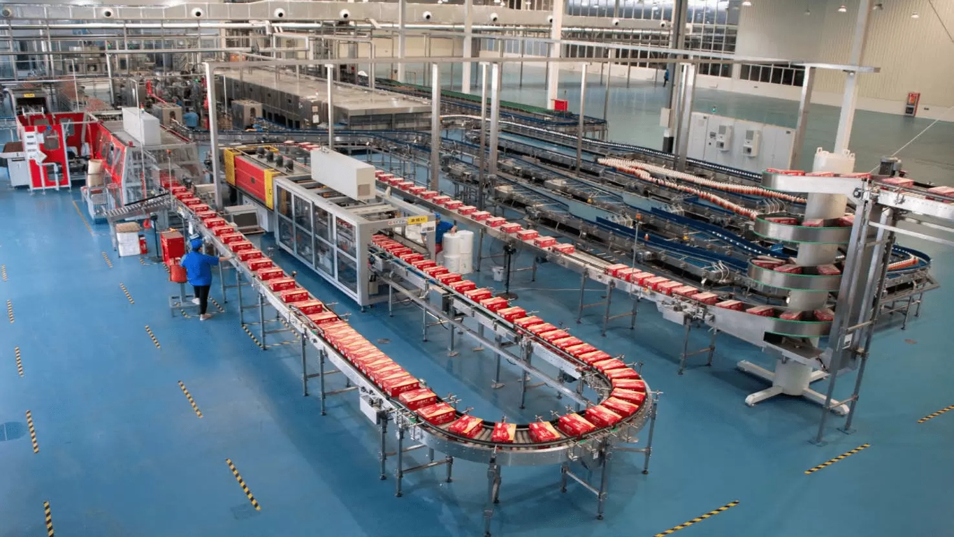
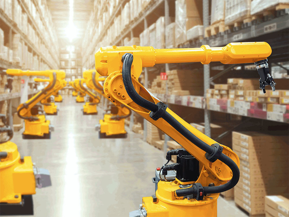
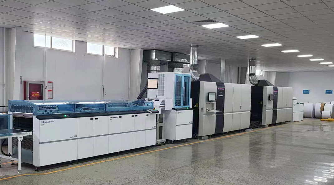
| Application | Medical industry/Robot industry/Automation industry |
| Specification | Standard |
| Origin | Dongguan(Mainland) |
| Production Capacity | 500000 PCS/Year |
| Product | Standard timing pulley AT5/AT10 |
| Customized | OEM, drawings or samples customized |
| Basic Shape | Type A/B/D/E/F/K |
| Surface Treatment | Clear anodizing, Black anodizing, Hard anodizing, Nickel plating, Black oxide |
| Material | 6061(aluminum);S45C(45# steel);SUS304(stainless steel) |
| Bore | Through hole, Tapped hole, Counterbore, Keyway |
| Tolerance Control | Outer diameter ±0.005mm Length diameter ±0.005mm |
| Standard | DIN, ISO/GB, AGMA, JIS |
| Teeth Accuracy | DIN, ISO/GB Class 4, AGMA Class 13, JIS Class 0 |
| Weight | Max 15 Tons |
| Testing Equipment | Projecting apparatus, salt spray test, durometer, and coating thickness tester, 2D projector |
| Producing Equipment | CNC machine, automatic lathe machine, stamping machine, CNC milling machine, rolling machine, lasering, tag grinding machine etc. |
| Machining Process | Gear hobbing, Gear milling, Gear shaping, Gear broaching, Gear shaving, Gear grinding and Gear lapping |
| Application Industry | Robot industry, Medical industry, Manufacturing machine industry, Automation industry, 3C industry equipment, Packaging industry, UAV industry, New energy industry |