Position: Home > News Center > Industry News > How Cross Roller Slide Eliminates Moment-Induced Deflection in Precision Linear Motion
How Cross Roller Slide Eliminates Moment-Induced Deflection in Precision Linear Motion
Jun. 24, 2026 Views:5
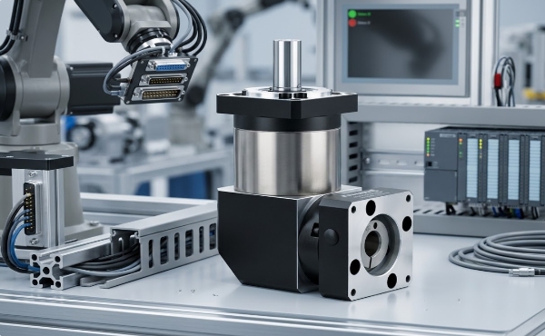
Standard recirculating ball linear guides achieve excellent performance under pure radial or axial loads, but their load capacity degradates rapidly when subjected to overturning moments—the combination of radial force and offset that creates rotational torque about the guide's longitudinal axis. In precision automation, semiconductor equipment, and optical positioning systems, these moments are not exceptional conditions but routine operational states. A vertically mounted stage with an offset payload, a gantry system with asymmetric tooling, or a multi-axis alignment platform with cantilevered sensors all impose moment loads that ball guides handle through increased preload, larger rail sections, or redundant guide pairs—all of which increase friction, envelope size, and cost without addressing the fundamental structural limitation.
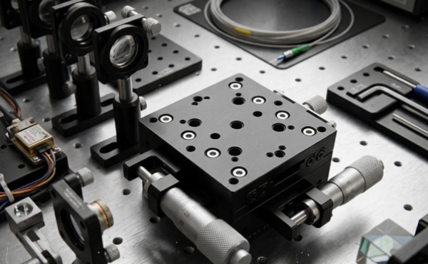
The iHF Cross Roller Slide from iHF Group represents an alternative linear motion architecture engineered specifically for applications where combined loading—including significant moment components—is inherent to the motion profile. By arranging cylindrical rollers in orthogonal V-groove raceways at 90-degree intervals, the cross roller design distributes load across four contact lines rather than two, providing inherent moment resistance without preload-dependent friction penalties.
Cross Roller Architecture: The Geometry of Multi-Directional Load Capacity
V-Groove Raceways and Orthogonal Roller Arrangement
In the iHF Cross Roller Slide, precision-ground cylindrical rollers are arranged alternately at 90 degrees to one another within V-groove raceways machined into the rail and carriage. Each roller contacts the raceway at two points, creating a total of four load-bearing contact lines per roller set. When a vertical (radial) load is applied, the horizontal rollers carry the primary load while the vertical rollers provide lateral constraint. When a horizontal (lateral) load is applied, the load distribution reverses. When an overturning moment is applied, the diagonal contact pairs on opposite sides of the guide resist the rotational tendency through differential loading.
This geometry contrasts fundamentally with ball guides, where load is carried at two Gothic-arch contact points per ball, and moment resistance depends entirely on preload-induced contact angle multiplication. The cross roller architecture achieves equivalent moment capacity at substantially lower preload levels—or significantly higher moment capacity at equivalent preload—because the orthogonal roller arrangement creates inherent geometric constraint rather than relying on elastic deformation for stability.
Preload and Friction Characteristics
Preload in linear guides eliminates internal clearance to prevent backlash and increase stiffness, but it introduces sliding friction proportional to preload magnitude. In ball guides, the moment capacity required for precision applications often demands preload levels that increase starting friction by 200-300% compared to clearance-fit configurations.
The iHF Cross Roller Slide achieves equivalent stiffness and moment capacity with preload levels 40-60% lower than comparable ball guide systems. This reduction translates directly into lower drive torque requirements, reduced motor sizing, decreased heat generation, and extended lubricant life. For applications where smooth motion at low speeds is critical—laser interferometry stages, atomic force microscope scanners, or precision dispensing systems—the lower friction ripple of cross roller slides eliminates the stick-slip phenomena that ball guide preload can induce.
Precision Manufacturing and Dimensional Control
Raceway Grinding and Roller Sorting
The performance of a cross roller slide depends on the geometric accuracy of the V-groove raceways and the dimensional uniformity of the roller population. iHF Group's manufacturing process employs CNC profile grinding of raceways with form accuracy within 1 micrometer and surface finish below Ra 0.2 micrometers. This precision ensures that roller contact occurs across the full theoretical contact line rather than concentrating at high points that would cause localized stress and premature fatigue.
Rollers are precision-ground and sorted into diameter classes with 0.5-micrometer granularity. Each iHF Cross Roller Slide is assembled with rollers selected from matched diameter classes to ensure uniform load distribution across all contact lines. This sorting discipline prevents the load concentration that occurs when rollers of mixed diameter share a raceway, where larger rollers carry disproportionate load and smaller rollers provide inadequate constraint.
Straightness and Parallelism Verification
After assembly, each slide undergoes straightness measurement using laser interferometry or precision granite reference surfaces. Straightness specifications of 3 micrometers per 100mm travel length are standard, with 1-micrometer precision grades available for metrology and semiconductor applications. Parallelism between rail and carriage reference surfaces is verified to within 2 micrometers over the full travel length, ensuring that multi-axis stacked configurations maintain orthogonal relationships without cumulative error.
Load Capacity and Stiffness Engineering
Static and Dynamic Load Ratings
The iHF Cross Roller Slide load ratings are calculated per ISO 14728-1, with static load capacity (C₀) representing the load that induces permanent deformation of 0.0001 times the roller diameter at the most heavily loaded contact, and dynamic load capacity (C) representing the load under which 90% of identical slides achieve 100km travel life.
For a typical iHF Cross Roller Slide with 15mm roller diameter and 30mm rail width, static load capacity exceeds 50kN in the radial direction, 30kN in the lateral direction, and moment capacity of 500 Nm in pitch and yaw axes. These values substantially exceed those of ball guides with equivalent envelope dimensions, enabling compact machine designs that would require significantly larger ball guide sections or dual-rail configurations.
Stiffness and Deflection Under Moment Loading
The critical performance differentiator for cross roller slides is deflection under moment loading. When an overturning moment is applied, the carriage rotates about the rail's longitudinal axis by an angle proportional to the moment and inversely proportional to the torsional stiffness. The iHF Cross Roller Slide achieves angular stiffness of 500-800 Nm/arc-minute for standard configurations, compared to 150-250 Nm/arc-minute for equivalent ball guides. This 3:1 to 4:1 stiffness advantage translates directly into maintained positional accuracy under varying payload conditions—a decisive factor in precision automation where tool center point deflection must remain within micrometer tolerances.
Application Engineering: Where Cross Roller Slides Deliver Differentiated Value
Semiconductor Wafer Handling and Inspection
Wafer stages in lithography, inspection, and probe testing equipment operate in vacuum or cleanroom environments with sub-micrometer positioning requirements. The iHF Cross Roller Slide's low particle generation (no recirculating ball return tubes), vacuum compatibility, and high stiffness-to-mass ratio make it optimal for these applications. iHF Group provides vacuum-baked lubricants and low-outgassing materials for integration into EUV lithography and electron beam inspection systems.
Precision Optical Alignment Systems
Laser beam steering, interferometer reference arm positioning, and adaptive optic alignment require linear motion with nanometer-scale resolution and minimal angular deviation. The iHF Cross Roller Slide's low friction ripple and high torsional stiffness enable piezoelectric or voice coil drives to achieve smooth, continuous motion without the dithering that ball guide friction variation can introduce.
Medical Imaging and Radiation Therapy
CT scanner gantries, linear accelerator patient positioning tables, and surgical robot arms require linear motion with high load capacity, radiation resistance, and maintenance accessibility. The iHF Cross Roller Slide's open architecture (no recirculating elements to trap debris) and stainless steel construction options satisfy these requirements with service intervals exceeding 10,000 hours.
Metrology and Coordinate Measuring Machines
CMM axes and surface profilometer stages demand geometric accuracy that does not degrade under probe contact forces or varying workpiece masses. The iHF Cross Roller Slide's inherent moment capacity maintains straightness and squareness under these variable loading conditions, where ball guides would require continuous recalibration or excessive structural mass to compensate for compliance.
视频
FAQ
Q: What is the maximum travel length available for the iHF Cross Roller Slide?
A: Standard travel lengths range from 25mm to 1,500mm in 25mm increments, with custom lengths available up to 3,000mm for specialized applications. Longer travels require consideration of rail deflection under self-weight and applied loads; iHF Group provides structural analysis to determine optimal rail section and support spacing for specific configurations.
Q: Can the iHF Cross Roller Slide operate without lubrication in cleanroom environments?
A: While full dry operation is possible with specialized coatings and materials, typical cleanroom applications employ minimal lubrication with perfluoropolyether (PFPE) greases that exhibit extremely low vapor pressure and particle generation. iHF Group's cleanroom-compatible slides are assembled and packaged in Class 100 environments with validated cleaning protocols.
Q: How does the iHF Cross Roller Slide compare in cost to equivalent ball guide systems?
A: Unit cost is typically 20-40% higher than comparable ball guides, but total system cost often favors cross roller architecture when the elimination of dual-rail configurations, reduced motor sizing from lower friction, and extended maintenance intervals are incorporated. iHF Group provides total cost of ownership analysis for specific application requirements.
Q: What is the recommended preload level, and can it be adjusted in the field?
A: Standard preload is factory-set through selective roller diameter matching and shim adjustment, typically achieving light preload (2-4% of dynamic load capacity) for general automation or medium preload (5-8%) for precision applications. Preload adjustment requires disassembly and roller replacement; iHF Group recommends factory service for preload modification to maintain performance specifications.
Q: Are stainless steel or corrosion-resistant versions available?
A: Yes, iHF Group offers 440C stainless steel raceways and rollers for corrosive or cleanroom environments, and 304 stainless steel housings for washdown applications. Ceramic roller options (silicon nitride) are available for extreme corrosion resistance or electrical isolation requirements.
This website uses cookies to provide you with a safer and more personal experience. By accepting, you agree to the Cookie Policy and the use of cookies for advertising and analytics purposes.


 EN
EN en
en vi
vi it
it es
es th
th tr
tr ja
ja pt
pt ko
ko ru
ru fr
fr de
de ar
ar Request Quote